| Set CAD-format | ||
|---|---|---|
| Drawbar D25-686, Self-Lifting | CADPDFRFQ |
Preview


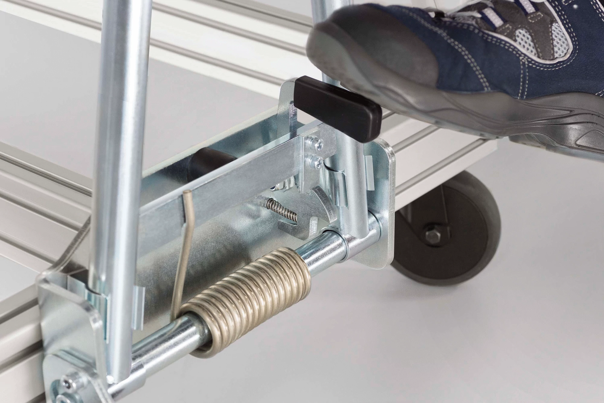
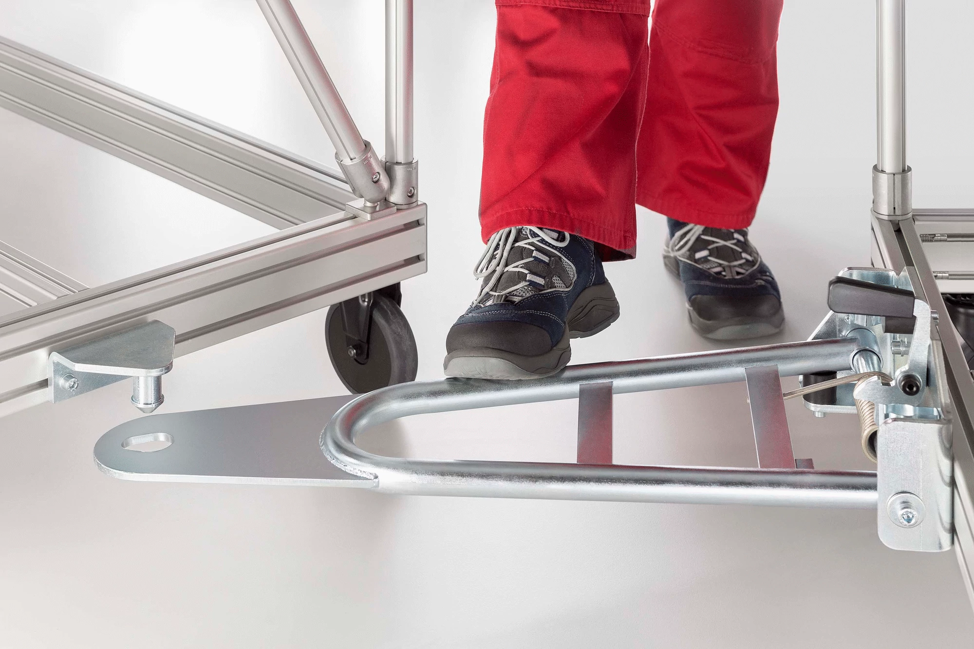
Preassembled Drawbar D25-650, St, bright zinc-plated Impact Buffer M8 D30x30, NBR Spring clip set D30, St, stainless Torsion spring 6.5×52, St, stainless
| Set CAD-format | ||
|---|---|---|
| Drawbar D25-686, Self-Lifting | CADPDFRFQ |
Preview
Scope of Delivery
Preassembled Drawbar D25-650, St, bright zinc-plated Impact Buffer M8 D30x30, NBR Spring clip set D30, St, stainless Torsion spring 6.5x52, St, stainless
Properties
| line 8 | line 8 |
|---|---|
| ESD-safe | Yes |
| Weight | m = 8.9 kg |
| Delivery unit | 1 set |
| Material | St, bright zinc-plated |