


| Set CAD-format |
|---|
Preview
 Kieli
Kieli


Configurated product data
Nothing generated yet
You must configurate your product below before requesting quote| Set CAD-format |
|---|
Preview
Properties
| line 8 | line 8 |
|---|---|
| ESD-safe | No |
| Cross-sectional area | A = 11.41 cm2 |
| Moment of Inertia, torsional | It = 2.41 cm4 |
| Moment of Inertia, x-axis | Ix = 84.49 cm4 |
| Moment of Inertia, y-axis | Iy = 16.61 cm4 |
| Weight | m = 3.1 kg/m |
| Delivery unit | cut-off max. 6000 mm |
| Material | Al, anodized |
| Colour | natural |

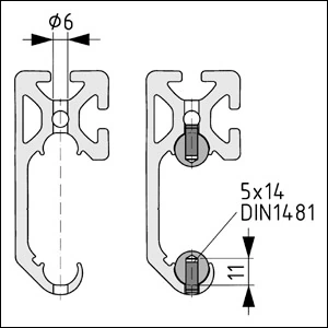
The following points must be taken into account when installing the guiding shafts: > Preparation for pinning Shafts D10 or D14 by drilling a single blind hole into each shaft at any point using a carbide-tipped drill. Shaft D6 does not need to be pinned. The Shaft is best drilled using the Combination Drilling Jig for Shafts (Section 9.2 Jigs and Tools). > Drill the through bores into the C-Rail Profile at the same point. > Press a dowel pin DIN 1481-4x10 into Shaft D10 or dowel pin DIN 1481-5x14 into Shaft D14.

> Using the Mounting Aid for Shafts (Section 9.2 Jigs and Tools), an appropriate round steel bar for a lever, and a profile for locating the Mounting Aid, the pre- greased guiding shafts are pressed into the C-Rail Profiles.
