


| Set CAD-format | ||
|---|---|---|
| Adjustable Foot 8 M20x40 | CADPDFRFQ |
Preview


2 T-Slot Nuts V 8 St M6, bright zinc-plated 2 Countersunk Screws DIN 7991 M6x14 1 flange for Adjustable Foot 8 M20x40 1 spindle for Adjustable Foot 8 M20x40
| Set CAD-format | ||
|---|---|---|
| Adjustable Foot 8 M20x40 | CADPDFRFQ |
Preview
Scope of Delivery
2 T-Slot Nuts V 8 St M6, bright zinc-plated 2 Countersunk Screws DIN 7991 M6x14 1 flange for Adjustable Foot 8 M20x40 1 spindle for Adjustable Foot 8 M20x40
Properties
| line 8 | line 8 |
|---|---|
| ESD-safe | No |
| Weight | m = 265 g |
| Delivery unit | 1 set |
| Status on delivery | Preassembled |
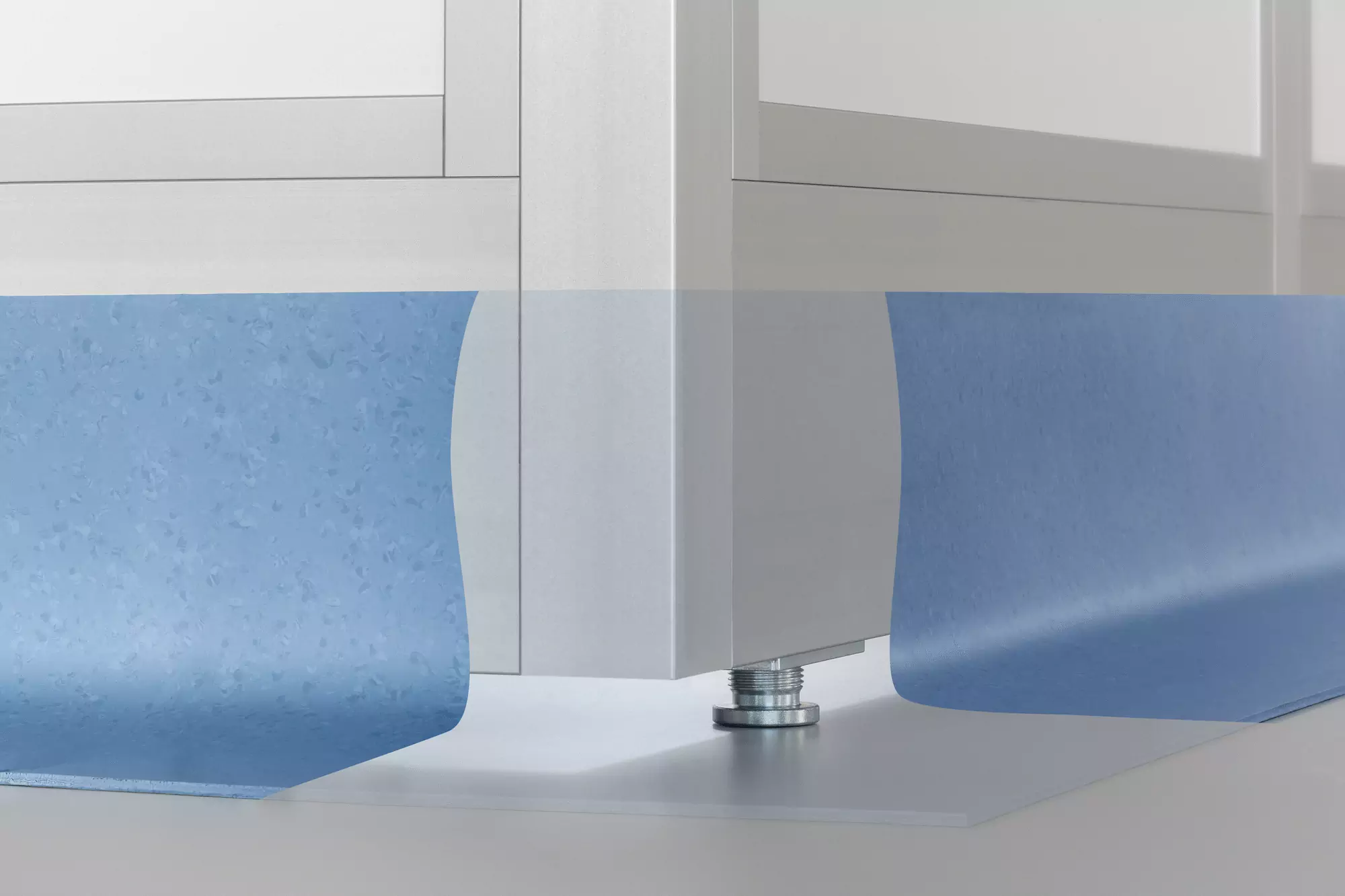
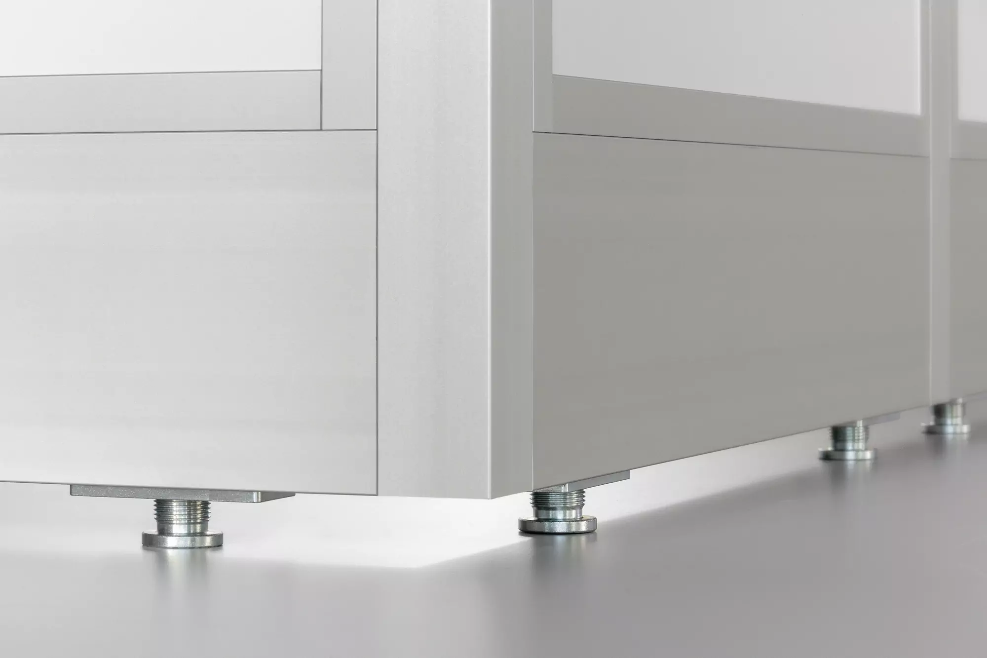

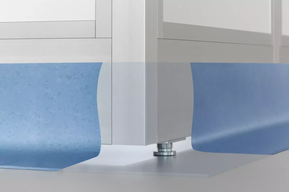
Installation sequence for Adjustable Foot 8 M20x40 and Screw Anchor when using profiles that are 40 mm wide: 1. Drill ⌀24 mm through hole (from both sides, if necessary) 2. Insert and fasten Adjustable Foot 3. Use hex key to level frame from above 4. Drill hole in floor and clear out hole 5. Introduce Screw Anchor from above and tighten securely in place

Installation sequence for Adjustable Foot 8 M20x40 when using profiles that are 80 mm wide: 1. Drill ⌀24 mm through hole (from both sides, if necessary) 2. Insert Adjustable Foot and fasten flange to two parallel grooves 3. Use hex key to level frame from above 4. Fit Screw Anchor as described above
